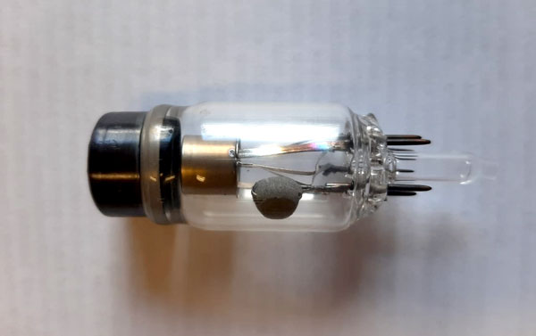
X-ray electronic tube, small-sized, three-electrode, with a grounded anode
The exterior construction does not use rubber, composites, etc., except for metal and glass.
The outer surface of the tube is chemically neutral and chemically passive.
X-RAY TUBE PARAMETERS:
Tube anode material ……………………………………………………….. Beryllium
Shape of the tube focal spot ……………………………………………….Round
The size of tube focal spot in the range of anode
voltage Ua = 10 … 15 kV and anode
power Pa = 0 … 5W, no more (mm) ……………………………………0,5
Sputtering of the tube anode…………………………………………… Copper
The anode spot is measured at a radiation intensity level of 50% of the peak value.
PURPOSE OF TUBE ELECTRODES:
Anode – an electrode that is an X-ray source.
Cathode – an electrode that is a source of electrons. Anode voltage is applied to the cathode.
Venelt – is a tube electrode, by changing the voltage on which the anode current of the tube is controlled.
Glow – is an additional electrode of the tube which is supplied by voltage of the tube cathode heater.
ELECTRICAL PARAMETERS OF THE TUBE:
Working voltage at the anode Ua, (kV), (1) ……………………………….….. — 10
Limiting anode voltage Ualimit, (kV), (1) ………………………………………. — 15
Maximum permissible anode power, Pamax, not less, (W), (2) ……..5
Maximum permissible voltage range on
venelt Uvmax, (V), (3) ……………………………………………………………………… 0… — 150
Venelt tube clamping voltage (Ua = Ualimit,
Ia <1mkA, Ivb no more, (B), (3) …………………………………………….……….-120
Tube cut-on voltage on the venelt (Ua = 15kV,
Ia = 200 μA, Ivco, not less (V), (3) ……………………………………………..….. — 4
Nominal effective value filament supply voltage, In, (V), (4) ……… 6.3
Allowable voltage spread heating supply (%) ……………………………… ± 5
Tube filament supply current at steady state
mode at I = In, In, no more……………………………………………………………… 0.3 A
(1) The voltage is set relative to the grounded anode of the tube.
(2) At a temperature at the base of the anode glass (the place of its adhesion to the glass balloon) no more than 70˚С.
(3) The voltage is set relative to the tube cathode.
(4) It is allowed to supply the cathode heater with an alternating voltage that differs in shape from a sinusoidal one, with a frequency of up to 250 kHz.
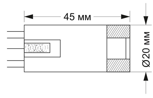
DIMENSIONS:
Diameter — 20 mm.
Length — 45 mm.
The greatest weight is 12 gr.
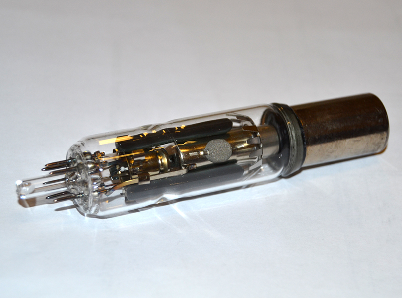
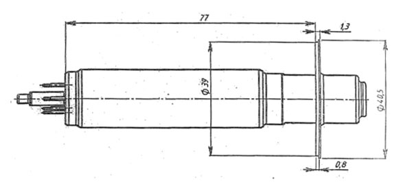
X-ray electronic tube, small-sized, four-electrode, metal-glass, with a grounded anode
X-ray electronic tube, small-sized, four-electrode, metal-glass, with a grounded anode.
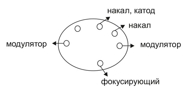
PURPOSE OF TUBE ELECTRODES:
Anode – is an electrode that is an X-ray source. The anode is electrically connected to the flange.
Cathode – is an electrode that is a source of electrons. Anode voltage is applied to the cathode.
Venelt – is a tube electrode, by changing the voltage on which the anode current of the tube is controlled.
Glow – is an additional electrode of the tube which is supplied by voltage of the tube cathode heater.
Focusing electrode controls – the diameter of the electron spot on the anode.
X-RAY TUBE PARAMETERS:
Tube anode material. ………………………………………………………… Beryllium
The shape of the focal spot of the tube ………………………………… Round
Tube focal spot size in the range of anode voltages Ua = 25 … 40kV and anode power Pa = 0 … 5W, no more (microns) ……………………… 10-30
Sputtering on the tube anode ………………………………………..……. Molybdenum
The anode spot is measured at a radiation intensity level of 50% of the peak value.
ELECTRICAL PARAMETERS OF THE PIPE:
Working voltage at the anode Ua, (kV), (1) ……………………………. — 40
Ultimate anode voltage Ualimit, (kV), (1) ………………………………. — 45
Maximum permissible anode power, Pmax, not less, (W), (2) .. 5 (10)
Maximum permissible voltage range on venelt
Uvmax, (V), (3) ………………………………………………………………… ..0… — 150
Venelt tube clamping voltage (Ua = Ualimit, Ia <1mkA,
Ivc no more, (V), (3) ……………………………………………………………….-120
Tube cut-on voltage on the venelt (Ua = 15kV,
Ia = 200 μA, Ivco, not less (V), (3) ……………………..………………….. — 4
Voltage range on the focusing electrode Ufe, kV ……………………. + 3-10
Rated r.m.s. voltage filament supply, Un, (V), (4) ……………………… 6,3
Allowable spread of values of heating supply voltage (%) ……… ± 5
Tube filament supply current in steady state at I = In,
In, not more, (5) …………………………………………………………….…… 90mA 0.3 A
The sign of the control voltage is indicated relative to the cathode of the tube. There are two versions with an anode substrate of beryllium (5W) and diamond (10W). The cathode is heated indirectly.
(1) The voltage is set relative to the grounded anode of the tube.
(2) At a temperature at the base of the anode glass (the place of its adhesion to the glass cylinder) no more than 70˚С.
(3) The voltage is set relative to the tube cathode.
(4) It is allowed to supply the cathode heater with an alternating voltage that differs in shape from a sinusoidal one, with a frequency of up to 250 kHz.
(5) There are two options for cathodes with different filament currents.
OVERALL DIMENSIONS OF THE PIPE:
The stability of the position of the electronic spot is high. It is determined by the stability of the supply voltage (anode voltage and focusing electrode voltage) from the power supply.